18 December, 2011

CONCEPT CARS

The Top 5 Most Bizarre Concept Cars

While there are many people who are looking for a new car ,here is a list of the top five most bizarre concept cars built by various manufacturers in the past 20 years.

Nissan Land Glider – One of Nissan’s zero-emission concepts, the Land Glider concept makes the car lean when you turn because of a computer controlled steering system. The driver sits in the centre, and there is a spot for a passenger behind them. The narrow car has replaced the steering wheel with a flight yoke, while there’s also a futuristic dashboard and there are monitors to cater for the fact that there are no rear view mirrors in the car.

Heuliez Friendly – It’s almost a mini campervan that is powered by electrons. It is a friendly looking, good for the environment concept that debuted at the Paris Motor Show back in 2008. With three different lengths and motors, this car sits you and two friends and can reach 70 miles per hour with a battery usage of around 140 miles.

Renault Z.E. – One of the bizarre concepts that has made waves in the market in this car from Renault. The Z.E. is used on a battery pack with electrons coming from a lithium ion battery pack. The body panels and heat reflecting paint ensure that the car is insulated, and it is the temperature regulation that lends itself to a reduced climate control load. What it does, ultimately, is lower energy consumption while have modern comforts.

Venturi Volage – An all-electric, carbon fiber race car, this hand-made car is a compact unit using electric drive motors. Each wheel has two motors, with one for propulsion and the other for suspension. The low centre of gravity helps to enhance the performance of the vehicle.

Mazda Kiyora – Part of the “flow” concept vehicles, this car has a look of a spaceship, more than an automobile but the 1.3 litre engine it boasts allows you to calmly cruise the urban streets. This next-generation compact car is known for high fuel-efficiency and is the next step into an urban car to replace their current line.

With many people thinking about lowering their emissions, it’s a great time to be buying concept cars for having in and around the city. Known for stylish interiors, exteriors and designs these are the future of motoring.

06 April, 2011

KERS

The acronym KERS stands for Kinetic Energy Recovery System. The device recovers the kinetic energy that is present in the waste heat created by the car’s braking process. It stores that energy and converts it into power that can be called upon to boost acceleration.

There are principally two types of system - battery (electrical) and flywheel (mechanical). Electrical systems use a motor-generator incorporated in the car’s transmission which converts mechanical energy into electrical energy and vice-versa. Once the energy has been harnessed, it is stored in a battery and released when required.


Mechanical systems capture braking energy and use it to turn a small flywheel which can spin at up to 80,000 rpm. When extra power is required, the flywheel is connected to the car’s rear wheels. In contrast to an electrical KERS, the mechanical energy doesn’t change state and is therefore more efficient.

There is one other option available - hydraulic KERS, where braking energy is used to accumulate hydraulic pressure which is then sent to the wheels when required.

This is mostly used in F1 Cars.

26 September, 2006

ECOSYSTEM ELEVATORS

Two types of elevators, which are hydraulic and traction, have been widely used as vertical transportation equipment. Hydraulic elevator has lower ownership costs and can be quickly installed if compared to traction elevators.Yet the hydraulic elevator is noisy, slow with poorer ride quality, and it uses a lot of energy and has the potential for environmental damage from leaking hydraulic fluid. On the other hand, the traction type is faster and smoother but it costs more to buy and own. In addition, both types of elevators can slow building completions with their special construction requirements.So there is a need to improve the technology of the Elevators.

NOW THE IMPROVED TECHNOLOGY:

EcoSystem is a family of AC gearless elevators developed by Montgomery Kone. The members of the EcoSystem family are EcoSpace and MonoSpace . These products are used in simplex or duplex installations for 2-10 landings, up to 80' of travel and operate at 200 fpm. EcoSpace has a controller closet located adjacent to the hoistway at the top elevator landing. MonoSpace is differentiated from EcoSpace by having a controller closet built into the front wall of the hoistway at the top landing.

EcoSystem uses EcoDisc hoisting machine, which is a compact, powerful and lightweight permanent magnet motor. EcoDisc has two independent brakes that make it safe. It consists of an AC gearless motor of axial synchronous design with an integrated traction sheave, brake flange and rotor. Unlike hydraulic elevators, EcoSystem powered by EcoDisc requires no hydraulic fluid, which can contaminate up to 250,000 gallons of groundwater with even a one-quart leak. Since EcoDisc is compact and lightweight, there is no penthouse or large machine room required.


ADVANTAGES:
  • EcoSystem is ecologically safe since it has no hydraulic fluid to harm the environment.
  • With its AC gearless technology, EcoSystem can lower power consumption by 40 percent, compared to conventional AC-powered traction elevators.
  • Since EcoSystem requires only a small machine room at the side of the elevator hoistway, it saves space, eliminates weight stress on the building, and simplifies installation.
  • EcoSystem installation is simple and its cost is reduced by eliminating expensive scaffolding or craneage, allowing simultaneous construction of the elevator with the rest of the building. Initial building costs for an emergency generator are less due to the lower starting amperage of the machine.
LIMITATION:
The EcoSystem elevators can only be used for lifting the maximum weight of 2,500 lbs. up to about 8 stories.

09 September, 2006

MAGNETIC LEVIATION

There are three different approaches to the technology of magnetic levitation train systems have been developed.

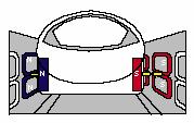
The first, called electromagnetic suspension (EMS), uses conventional electromagnets mounted at the ends of a pair of structures under the train; the structures wrap around and under each side of the guideway. The magnets are attracted up towards laminated iron rails in the guideway and lift the train. However, this system is inherently unstable; the distance between the electromagnets and the guideway, which is about 10 mm (3/8 in), must be continuously monitored and adjusted by computer to prevent the train from hitting the guideway.

The second design, called electrodynamics’ suspension (EDS), uses the opposing force between magnets on the vehicle and electrically conductive strips or coils in the guideway to levitate the train. This approach is inherently stable, and does not require continued monitoring and adjustment; there is also a relatively large clearance between the guideway and the vehicle, typically 100 to 150 mm (4 to 6 in). However, an EDS maglev system uses superconducting magnets, which are more expensive than conventional electromagnets and require a refrigeration system in the train to keep them cooled to low temperatures. Both EMS and EDS systems use a magnetic wave traveling along the guideway to propel the maglev train while it is suspended above the track.

The third, a newer, perhaps less-expensive, system is called "Inductrack". The technique has a load-carrying ability related to the speed of the vehicle, because it depends on currents induced in a passive electromagnetic array by permanent magnets. In the prototype, the permanent magnets are in a cart; horizontally to provide lift, and vertically to provide stability. The array of wire loops is in the track. The magnets and cart are un-powered, except by the speed of the cart. Inductrack was originally developed as a magnetic motor and bearing for a flywheel to store power. With only slight design changes, the bearings were unrolled into a linear track. Inductrack was developed by physicist Richard Post at Lawrence Livermore National Laboratory. Inductrack uses Halbach arrays for stabilization. They also have a magnetic field on the track side only, thus reducing any potential effects on the passengers.

Levitation: The "8" figured levitation coils are installed on the sidewalls of the guideway. When the on-board superconducting magnets pass at a high speed about several centimeters below the center of these coils, an electric current is induced within the coils, which then act as electromagnets temporarily. As a result, there are forces which push the superconducting magnet upwards and ones which pull them upwards simultaneously, thereby levitating the Maglev vehicle.
Lateral guidance: The levitation coils (magnets) are connected on both sides of the guideway. In a running Maglev vehicle, a repelling force between the train and the guideway on one side (N repels N), and on the other side of the train between the train and the guideway (S repels S), keeps the car at the center of the guideway.

Propulsion:
A repelling force and an attracting force created between the magnets on the train and in the guideway (track) are used to propel (move) the vehicle forward. The magnetic coils located on the sidewalls on both sides of the guideway (track) are powered by an alternating current from the station, creating a shifting magnetic field on the guideway.The superconducting magnets on the train are attracted and pushed by the shifting field in the guideway (track), propelling the Maglev

Superconducting magnet: Super conductivity is a phenomenon where electric current flows with zero resistance in a material such as niobium germanium compound, ceramic metal oxide etc. In maglev system the first compound is used for making the superconducting magnet. To keep it superconducting state, it is immerged into liquid helium at 23.2K.


E.M.S Technology:
Propulsion:
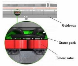
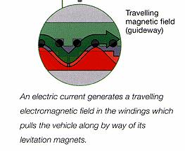
In E.M.S system the train surrounds the guideway.The is propelled by linear induction motor same as E.D.S. system. Here stator pack is installed in guideway and rotor coil is installed in train. By feeding 3 phases alternating current in the rotor coil, the train is pulled towards the shifting magnetic field, produced by that 3 phase current without contact.This is shown in picture.

The speed of the train is varied by changing the frequency of the alternating current. Changing the direction of the shifting magnetic field results in non contact braking of the train because motor is converted into generator. The braking energy can then be fed back to the power grid in form of electric energy.


Leviation and Guidance:
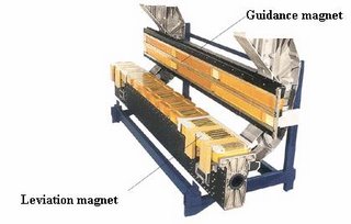
Leviation is created by attraction between electromagnet, installed in train and ferromagnetic stator pack in the guidway.Guidance is also occurred by the guidance magnet, installed in sidewalls of the train. This maintains an equal gap (10mm) between train and guide way and to keep the train in centre.
The leviation system is powered by on board batteries, thus independent of the propulsion system. While traveling the on board batteries are recharged by the linear generators integrated into the levitation magnets.

18 August, 2006

BRAKING WITH SBC

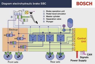
This is the world‘s first brake-by-Wire system in a passenger car, where Mechanical and Hydraulic connections are replaced by electronically controlled functions. A travel sensor and pressure sensor measure speed and power from the driver stepping on the brake pedal. The information received is processed by the control unit (ESP), which sends control signals via CAN to the pressure modulator. The hydraulic unit independently regulates the braking pressure to the individual wheels. This brake pressure is fed into each brake caliper from a high-pressure accumulator via the hydraulic unit. The brake fluid is permanently pressurized in hydraulic unit to approx. 140 bars, so the SBC can implement the brake command instantaneously. The brake pressure for each wheel is calculated using information on the current driving conditions provided by the ESP (Electronic Stability Program). While cornering, higher brake pressure is applied to the outside wheels than the inside, which significantly increases stability while decelerating. If the brake pedal is depressed very quickly, yet not with sufficient force, the system concludes that it‘s an emergency and increases pressure up to the ABS control limit. Most cars with SBC are also fitted with a rain sensor which recognizes the starting of rain. It automatically removes water or salt film on the brake discs by very light regular braking impulses, which means the brake discs will be clean and dry when braking is required. Switching on the windshield wiper activates this function.
The system uses eight separate brake circuits for brake operation.

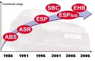
REVOLUTION OF SBC


CARS WITH SBC

1. Mercedes SL roadster (R230)
2. Mercedes E-Class sedan (W211) and Estate (S211) until mid 2006
3. Mercedes E-Class 4matic sedan (W211) and 4matic Estate (S211)
4. Mercedes SLR McLaren (C199)
5. Maybach 57 and 62 (W240)
6. Mercedes CLS coupe (C219)

ADVANTAGES OF SBC


1. SBC STOP: In stop-and-go traffic the vehicle brakes automatically, when the foot is lifted off the accelerator pedal ("Traffic Jam Assist"). It can be engaged under 10 MPH, using the cruise control lever and switches off automatically at higher speeds. It remains active under 40 MPH. When engaged the instrument cluster indicates "SBC S". One can also activate it on downhill slopes via cruise control, so the car won't speed over the set limit.
2. SBC SOFT STOP: In city traffic soft-stop supposedly allows soft, jerk less stopping.
3. SBC HOLD:A "drive-away assistant" prevents the vehicle from rolling backwards or forward when starting on a hill or steep incline.
4. DRY BRAKE:It is always activated when the windshield wipers run. The system then knows, that it rains and, with short brake pulses unnoticed by the driver, keeps the brake discs always dry and fully functional.
5. BRAKING IN A CURVE:Left: conventional. Right: with SBC
6. ELECTRONIC BRAKE PROPORTIONATING:EBP-allows brake proportioning
front to back and side to side.
7.No pedal vibration during ABS operation- eliminates "distraction"
to the driver during critical moments- indicator light in instrument
cluster signals traction loss.
8.Pressure reduction at standstill- reduces stress on components.
9. SHORTER STOPPING DISTANCE 10. BETTER BRAKE RESPONSE 11. EVEN WEAR ON BRAKE PAD LININGS

SENSOTRONIC BRAKE CONTROL (SBC)

Recently automated industry pays more attention on the improvement of the safety and comfort of their vehicle models and provides the latest car by incorporating the new technological innovations like Active body suspension (ABS), Electronic Stability Program (ESP), Sensotronic brake control (SBC) etc.
Sensotronic brake control is an innovative electro hydraulic brake system which gives maximumsafety and comfort on braking. Sensotronic Brake Control (SBC) is the name given to an innovative electronically controlled brake system.
With Sensotronic Brake Control, electric impulses are used to pass the driver's braking commands onto a microcomputer which processes various sensor signals simultaneously and, depending on the particular driving situation, calculates the optimum brake pressure for each wheel. As a result, SBC offers even greater active safety than conventional brake systems when braking in a corner or on a slippery surface. A high-pressure reservoir and electronically controllable valves ensure that maximum brake pressure is available much sooner.
To turn to the technical side: when drivers hit the brake pedal today, their foot moves a piston rod which is linked to the brake booster and the master brake cylinder. Depending on the pedal force, the master brake cylinder builds up the appropriate amount of pressure in the brake
lines which - in a tried and tested interaction of mechanics and hydraulics - then presses the brake pads against the brake discs via the wheel cylinders.